User Guide
Overview of iEDA
iEDA System Deployment Diagram
Tool Preparation
Environment
- Server Configuration
- Operating System: Ubuntu 20.04.5 LTS
- Process Environment: SkyWater PDK
Compilation and Construction
# Download the iEDA repository
git clone https://gitee.com/oscc-project/iEDA.git iEDA && cd iEDA
# Install compilation dependencies via apt, root privileges required
sudo bash build.sh -i apt
# Compile iEDA
bash build.sh -j 16
# If "Hello iEDA!" is output normally, the compilation is successful
./bin/iEDA -script scripts/hello.tcl
Copy ./bin/iEDA to the directory ./scripts/design/sky130_gcd
# Copy iEDA to the sky130 directory
cp./bin/iEDA scripts/design/sky130_gcd/.
Process File Preparation
Download SkyWater PDK
Copy the TechLEF file and LEF file to the directory ./scripts/foundry/sky130/lef
# Copy the TechLEF file to the directory `./scripts/foundry/sky130/lef`
cp <skywater130pdk_tlef_path>/*.tlef scripts/foundry/sky130/lef/.
# Copy the LEF file to the directory `./scripts/foundry/sky130/lef`
cp <skywater130pdk_lef_path>/*.lef scripts/foundry/sky130/lef/.
Copy the Lib file to ./scripts/foundry/sky130/lib
# Copy the Lib file to the directory `./scripts/foundry/sky130/lib`
cp <skywater130pdk_lib_path>/*.lib scripts/foundry/sky130/lib/.
Copy the sdc file to ./scripts/foundry/sky130/sdc
# Copy the sdc file to the directory `./scripts/foundry/sky130/sdc`
cp <skywater130pdk_sdc_path>/*.sdc scripts/foundry/sky130/sdc/.
Design File Preparation
Copy the .v Netlist file to the directory scripts/design/sky130_gcd/result/verilog
# Copy the `.v` file to the directory `./scripts/design/sky130_gcd/result/verilog`
cp <skywater130pdk_verilog_path>/gcd.v scripts/design/sky130_gcd/result/verilog/.
Tool Flow
This document takes running the physical backend design flow of the skywater PDK 130nm process as an example to illustrate how to configure parameters, run, and analyze the results of each point tool of iEDA.
Module Division
scripts
├── design                   # iEDA flows for different designs
│   ├── ispd18               # tbd
│   └── sky130_gcd           # flow of gcd in sky130
│       ├── iEDA
│       ├── iEDA_config      # iEDA parameters configuration files
│       ├── README.md
│       ├── result           # iEDA result output files
│       ├── run_iEDA_gui.py  # Python3 script for running all iEDA flow with GUI layout
│       ├── run_iEDA.py      # Python3 script for running all iEDA flow
│       ├── run_iEDA.sh      # POSIX shell script for running all iEDA flow
│       └── script           # TCL script files
├── foundry
│   ├── README.md
│   └── sky130               # SkyWater Open Source PDK
│       ├── lef              # lef files
│       ├── lib              # lib files
│       ├── sdc              # sdc files
│       └── spef             # folder for spef files if needed
└── hello.tcl                # Test running iEDA
Script Module Description
The script directory contains all the process scripts and result analysis and evaluation scripts required for the physical backend design, and is divided into modules by process and function; the process scripts can support the call of the top-level automated running script run_iEDA.py, and can also support independent running.
scripts/design/sky130_gcd/script
├── DB_script                           # Data process flow scripts
│   ├── db_init_lef.tcl                 # Initialize lef
│   ├── db_init_lib_drv.tcl             # Initialize lib only for flow of drv
│   ├── db_init_lib_fixfanout.tcl       # Initialize lib only for flow of fix fanout
│   ├── db_init_lib_hold.tcl            # Initialize lib only for flow of optimize hold
│   ├── db_init_lib_setup.tcl           # Initialize lib only for flow of optimize setup
│   ├── db_init_lib.tcl                 # Initialize lib for common flow
│   ├── db_init_sdc.tcl                 # Initialize sdc
│   ├── db_init_spef.tcl                # Initialize spef
│   ├── db_path_setting.tcl             # Set paths for all processing technology files, including TechLEF, LEF, Lib, sdc and spef
│   ├── run_db_checknet.tcl             # Check net connectivity based on data built by DEF (.def) and LEF (.lef &.tlef)
│   ├── run_db_report_evl.tcl           # Report wire length and congestion based on data built by DEF (.def) and LEF (.lef &.tlef)
│   ├── run_db.tcl                      # Test building data by DEF (.def) and LEF (.lef &.tlef)
│   ├── run_def_to_gds_text.tcl         # Transform data from DEF (.def) to GDSII (.gdsii)
│   ├── run_def_to_verilog.tcl          # Transform data from DEF (.def) to netlist (.v)
│   ├── run_netlist_to_def.tcl          # Transform data from netlist (.v) to DEF (.def)
│   └── run_read_verilog.tcl            # Test read verilog file (.v)
├── iCTS_script                         # CTS flow scripts
│   ├── run_iCTS_eval.tcl               # Report wire legnth for CTS result
│   ├── run_iCTS_STA.tcl                # Report CTS STA
│   └── run_iCTS.tcl                    # Run CTS
├── iDRC_script                         # DRC(Design Rule Check) flow scipts
│   ├── run_iDRC_gui.tcl                # Show GUI for DRC result
│   └── run_iDRC.tcl                    # Run DRC
├── iFP_script                          # Floorplan flow scripts
│   ├── module                          # Submodule for Floorplan scripts
│   │   ├── create_tracks.tcl           # Create tracks for routing layers
│   │   ├── pdn.tcl                     # Create pdn networks
│   │   └── set_clocknet.tcl            # Set clock net
│   └── run_iFP.tcl                     # Run Floorplan
├── iGUI_script                         # GUI flow scipts
│   └── run_iGUI.tcl                    # Run GUI
├── iNO_script                          # NO(Netlist Optimization) flow scipts
│   └── run_iNO_fix_fanout.tcl          # Run Fix Fanout
├── iPL_script                          # Placement flow scripts
│   ├── run_iPL_eval.tcl                # Report congestion statistics and wire legnth for Placement result
│   ├── run_iPL_filler.tcl              # Run standard cell filler
│   ├── run_iPL_gui.tcl                 # Run gui flow that shows Global Placement Processing result
│   ├── run_iPL_legalization_eval.tcl   # Report congestion statistics and wire legnth for Legalization result
│   ├── run_iPL_legalization.tcl        # Run Cell Legalization
│   └── run_iPL.tcl                     # Run Placement
├── iRT_script                          # Routing flow scripts
│   ├── run_iRT_DRC.tcl                 # Run DRC for Routing result
│   ├── run_iRT_eval.tcl                # Report wire legnth for Routing result
│   ├── run_iRT_STA.tcl                 # Run STA for Routing result
│   └── run_iRT.tcl                     # Run Routing
├── iSTA_script                         # STA flow scripts
│   ├── init_iSTA.tcl                   # STA initialization
│   ├── report_iSTA.tcl                 # Report STA result
│   └── run_iSTA.tcl                    # Run STA
└── iTO_script                          # TO(Timing Optimization) flow script
    ├── run_iTO_drv_STA.tcl             # Run STA for DRV result
    ├── run_iTO_drv.tcl                 # Run DRV
    ├── run_iTO_hold_STA.tcl            # Run STA for Fix Hold Violation result
    ├── run_iTO_hold.tcl                # Run Fix Hold Violation
    ├── run_iTO_setup_STA.tcl           # Run STA for Fix Setup Violation result
    └── run_iTO_setup.tcl               # Run Fix Setup Violation
Running the Flow
After preparing iEDA and process files, you can choose to automatically run the sky130 process script or run each point tool script step by step. All results are saved in the script/sky130/result folder by default
Basic Flow of the Flow
Whether running the top-level run_iEDA.py script automatically or running the point tool scripts separately, the scripts designed based on the iEDA platform have similar steps. The specific process is as follows <br>
Step 1 Path Setting <br>
First, the process environment path must be configured. To facilitate the search and configuration of path parameters, the paths of TechLEF, LEF, Lib, sdc, and spef are uniformly configured in the file ./script/DB_script/db_path_setting.tcl for the script, as shown in the following table
| Function | Configuration Command | Reference TCL Example |
|---|---|---|
| Set TechLef Path | set TECH_LEF_PATH xxx | set TECH_LEF_PATH "./lef/sky130_fd_sc_hs.tlef" |
| Set Lef Path | set LEF_PATH xxx | set LEF_PATH./lef/sky130_ef_io__com_bus_slice_10um.lef |
| Set Lib Path | set LIB_PATH xxx | set LIB_PATH./lib/sky130_dummy_io.lib |
| Set Fix Fanout Lib Path | set LIB_PATH_FIXFANOUT xxx | set LIB_PATH_FIXFANOUT./lib/sky130_dummy_io.lib |
| Set Fix DRV Violation Lib Path | set LIB_PATH_DRV xxx | set LIB_PATH_DRV./lib/sky130_dummy_io.lib |
| Set Fix Hold Violation Lib Path | set LIB_PATH_HOLD xxx | set LIB_PATH_HOLD./lib/sky130_dummy_io.lib |
| Set Fix Setup Violation Lib Path | set LIB_PATH_SETUP xxx | set LIB_PATH_SETUP./lib/sky130_dummy_io.lib |
| Set SDC Path | set SDC_PATH xxx | set SDC_PATH "./sdc/gcd.sdc" |
| Set SPEF Path | set SPEF_PATH xxx | set SPEF_PATH "./spef/xxx.spef" |
Step 2 Configure Point Tool Config <br>
The parameter settings Config of all point tools are in the path ./iEDA_config. You can view the Input and Output List in the later chapters to modify the corresponding point tool Config file
Step 3 Read.def Design File <br>
Taking CTS as an example, execute the def_init command to read the result after layout
#===========================================================
##   read def
#===========================================================
def_init -path./result/iPL_result.def
After steps 1 - 3, the data of Tech LEF, LEF, and DEF files will be loaded, which is a prerequisite for the startup of the point tool
Step 4 Start Point Tool <br>
Taking CTS as an example, execute the run_cts command to start the CTS process
#===========================================================
##   run CTS
#===========================================================
run_cts -config./iEDA_config/cts_default_config.json
Step 5 Save Point Tool Running Results <br>
Taking CTS as an example, after the point tool process is completed, the running results of the point tool are saved in the path ./result/
#===========================================================
##   Save def
#===========================================================
def_save -path./result/iCTS_result.def

#===========================================================
##   Save netlist
#===========================================================
netlist_save -path./result/iCTS_result.v -exclude_cell_names {}
Step 6 Output Report <br>
Taking CTS as an example, after the data is stored, the overall report related to the design result will be output, and the report path is stored in ./result/report/
#===========================================================
##   report
#===========================================================
report_db -path "./result/report/cts_db.rpt"
Step 7 Exit <br>
#===========================================================
##   Exit
#===========================================================
flow_exit
The above steps are the general process of executing a single point tool. Among them, steps 1 - 3 initialize the configuration and database and are necessary steps. After step 4, various point tools or module commands can be flexibly connected as needed <br>
Report Analysis
After the point tool runs, the analysis report will be stored in the path ./result/report, and the module division is shown in the following table <br>
| Report Type | Path | Description |
|---|---|---|
| Tech LEF, LEF, DEF Data Report | ./result/report | Analyze and count the data of the Design file, and report the detailed data of the PR process unit and net in detail |
| Wire Length, Congestion Evaluation Report | ./result/report/eval | Analyze and count the wire length, cell density, and routing congestion of the point tool output result |
| DRC Report | ./result/report/drc | Mainly detect the DRC violation situation after routing, and support GUI visual analysis |
Basic Information
Taking the result report after CTS as an example <br>
View the data report of CTS, and the path is ./result/report/cts_db.rpt <br>
+-----------------+-----------------------------+
| iEDA            | V23.03-OS-01                |
+-----------------+-----------------------------+
| Stage           | iCTS - Clock Tree Synthesis |
| Runtime         | 2.863340 s                  |
| Memmory         | 5745.216000 MB              |
|                 |                             |
| Design Name     | gcd                         |
| DEF&LEF Version | 5.8                         |
| DBU             | 1000                        |
+-----------------+-----------------------------+
The meanings of each label are shown in the following table <br>
| Label | Sample Value | Description |
|---|---|---|
| iEDA | V23.03-OS-01 | The current version number of iEDA |
| Stage | iCTS - Clock Tree Synthesis | The process stage of the current result. iCTS indicates that the current result is output by CTS |
| Runtime | 2.863340 s | The running time required for the current point tool to read the data and save the result |
| Memmory | 5745.216000 MB | The maximum peak memory required for the current point tool to read the data and save the result |
| Design Name | gcd | The design name |
| DEF&LEF Version | 5.8 | The version number of the current design's process file |
| DBU | 1000 | The number of unit lengths contained in 1 micron, used to convert DEF and Tech LEF parameter values (DATABASE MICRONS LEFconvertFactor) |
Design Data Report
Taking the Design data report after CTS as an example, the following explains the various parameters and labels of the report <br>
View the data report of CTS, and the path is ./result/report/cts_db.rpt <br>
Summary <br>
The Summary report is based on Tech LEF and DEF data, and counts the basic information of various data types <br>
Taking the Summary of the CTS result as an example <br>
###################################################################
Summary
+------------------------+----------------------------------------+
| Module                 | Value                                  |
+------------------------+----------------------------------------+
| DIE Area ( um^2 )      | 22513.194880 = 149.960000 * 150.128000 |
| DIE Usage              | 0.297306                               |
| CORE Area ( um^2 )     | 16893.489600 = 130.080000 * 129.870000 |
| CORE Usage             | 0.396206                               |
|                        |                                        |
| Number - Site          | 2                                      |
| Number - Row           | 39                                     |
| Number - Track         | 12                                     |
| Number - Layer         | 13                                     |
| Number - Routing Layer | 6                                      |
| Number - Cut Layer     | 5                                      |
| Number - GCell Grid    | 0                                      |
| Number - Cell Master   | 856                                    |
| Number - Via Rule      | 54                                     |
|                        |                                        |
| Number - IO Pin        | 56                                     |
| Number - Instance      | 941                                    |
| Number - Blockage      | 0                                      |
| Number - Filler        | 0                                      |
| Number - Net           | 683                                    |
| Number - Special Net   | 2                                      |
+------------------------+----------------------------------------+
The parameter descriptions of the report are shown in the following table
| Parameter Name                 | Tech LEF/LEF Keyword Field | DEF Keyword Field | Description                                                                   |
| :----------------------------- | :------------------------- | :--------------- | :----------------------------------------------------------------------------- |
| DIE Area ( um^2 )              |                           | DIEAREA          | Die area of the layout, in square microns                                      |
| DIE Usage                      |                           |                  | Utilization rate of the die layout, i.e., the area of all Instances in Design / Die area |
| CORE Area ( um^2 )             |                           |                  | Core area of the layout, in square microns. The area of the core is the sum of the areas of all standard cell ROWs |
| CORE Usag                      |                           |                  | Utilization rate of the core layout, i.e., the area of all Instances in Design / Core area |
| Number - Site                  | SITE                      |                  | Number of SITEs defined in Tech LEF                                             |
| Number - Row                   |                           | ROW              | Number of standard cell ROWs generated in the layout                            |
| Number - Track                 |                           | TRACKS           | Number of TRACKs generated in the layout                                        |
| Number - Layer                 | LAYER                     |                  | Total number of layers defined in Tech LEF                                      |
| Number - Routing Layer         | TYPE ROUTING ;            |                  | Number of routing layers defined in Tech LEF                                    |
| Number - Cut Layer             | TYPE CUT ;                |                  | Number of via layers defined in Tech LEF                                        |
| Number - GCell Grid            |                           | GCELLGRID        | Number of GCell Grids generated in the layout                                   |
| Number - Cell Master           | MACRO                     |                  | Number of all Cell Masters defined in LEF, including macro cells, standard cells, and filler cells |
| Number - Via Rule              | VIA `<br>` VIARULE        | VIAS             | Number of Via defined in LEF                                                    |
| Number - IO Pin                |                           | PINS             | Number of IO Pins generated in DEF                                             |
| Number - Instance              |                           | COMPONENTS       | Number of all Instances generated in DEF                                        |
| Number - Blockage              |                           | BLOCKAGES        | Number of all Blockages generated in DEF                                         |
| Number - Filler                |                           | FILLS            | Number of all Fillers generated in DEF                                           |
| Number - Net                   |                           | NETS             | Number of all Nets generated in DEF                                              |
| Number - Special Net           |                           | SPECIALNETS      | Number of all Special Nets generated in DEF                                      |
Summary - Instance <br>
Statistics of all Instance information by different classification rules <br>
Taking the result of CTS as an example <br>
Summary - Instance
+---------------+--------+--------------+------------+------------+
| Type          | Number | Number Ratio | Area       | Area Ratio |
+---------------+--------+--------------+------------+------------+
| All Instances | 941    | 1            | 7161635200 | 1          |
|               |        |              |            |            |
| Netlist       | 648    | 0.688629     | 6693304000 | 0.934606   |
| Physical      | 293    | 0.311371     | 468331200  | 0.0653945  |
| Timing        | 0      | 0            | 0          | 0          |
|               |        |              |            |            |
| Core          | 940    | 0.998937     | 7157635200 | 0.999441   |
| Core - logic  | 647    | 0.687566     | 6689304000 | 0.934047   |
| Pad           | 0      | 0            | 0          | 0          |
| Block         | 0      | 0            | 0          | 0          |
| Endcap        | 0      | 0            | 0          | 0          |
| Cover         | 0      | 0            | 0          | 0          |
| Ring          | 0      | 0            | 0          | 0          |
+---------------+--------+--------------+------------+------------+
The parameter description of the report is shown in the following table <br>
| Parameter Name       | Description                                                                          |
| :------------------- | :----------------------------------------------------------------------------------- |
| Type                 | Type of Instance                                                                     |
| Number               | Number of Instances counted                                                           |
| Number Ratio         | Ratio of the counted Instance number to the total number of Instances, i.e., the counted Instance number / the total number of Instances |
| Area                 | Total area of the counted Instance                                                    |
| Area Ratio           | Ratio of the area of the counted Instance to the total area of all Instances, i.e., the total area of the counted Instance / the total area of all Instances |
The classification description of the type Type is as follows <br>
- All Instances: All Instances
- Netlist: All Instance of the wire network type, corresponding to the keyword whose SOURCE attribute of COMPONENTS in DEF is NETLIST
- Physical: All Instance of the physical cell type, corresponding to the keyword whose SOURCE attribute of COMPONENTS in DEF is DIST
- Timing: All Instance used to change the timing of the wire network, such as Buffer, corresponding to the keyword whose SOURCE attribute of COMPONENTS in DEF is TIMING
- Core: The number of all standard cells in the Core area, corresponding to the CLASS attribute of MACRO in LEF being CORE
- Core - logic: The number of all non-filler standard cells in the Core area
- Pad: All I/O Pad Instance, corresponding to the CLASS attribute of MACRO in LEF being PAD
- Block: All Block Instance, corresponding to the CLASS attribute of MACRO in LEF being BLOCK
- Endcap: All Endcap Instance, corresponding to the CLASS attribute of MACRO in LEF being ENDCAP
- Cover: All Cover Instance, corresponding to the CLASS attribute of MACRO in LEF being COVER
- Ring: All Ring Instance, corresponding to the CLASS attribute of MACRO in LEF being RING
Summary - Net <br>
Statistics of all Net information by different classification rules <br>
Taking the result of CTS as an example <br>
Summary - Net
+----------------+--------+--------------+--------+--------------+
| Net Type       | Number | Number Ratio | Length | Length Ratio |
+----------------+--------+--------------+--------+--------------+
| All Nets       | 683    | 1            | 0      | 0            |
| Signal         | 674    | 0.986823     | 0      | 0            |
| Clock          | 9      | 0.0131772    | 0      | 0            |
| Power & Ground | 0      | 0            | 0      | 0            |
+----------------+--------+--------------+--------+--------------+
The parameter description of the report is shown in the following table <br>
| Parameter Name       | Description                                                                   |
| :------------------- | :---------------------------------------------------------------------------- |
| Net Type             | Type of Net                                                                  |
| Number               | Number of Nets counted                                                        |
| Number Ratio         | Ratio of the counted Net number to the total number of Nets, i.e., the counted Net number / the total number of Nets |
| Length               | Total length of the counted Net                                               |
| Length Ratio         | Ratio of the wire length of the counted Net to the total wire length of all Nets, i.e., the total length of the counted Net / the total length of all Nets |
The classification description of the type Net Type is as follows <br>
- All Nets: All Nets
- Signal: All signal Nets, corresponding to the USE attribute of NETS in DEF being SIGNAL
- Clock: All clock Nets, corresponding to the USE attribute of NETS in DEF being CLOCK
- Power & Ground: All power Nets, corresponding to the USE attribute of NETS in DEF being GROUND or POWER
Summary - Layer <br>
Statistics of data information of all layers <br>
Taking the result of CTS as an example <br>
Summary - Layer
+-------+-------------------+-------------------+------------------+--------------------+---------------------------+---------------------------+--------------------------+
| Layer | Net - Wire Length | Net - Wire Number | Net - Via Number | Net - Patch Number | Special Net - Wire Length | Special Net - Wire Number | Special Net - Via Number |
+-------+-------------------+-------------------+------------------+--------------------+---------------------------+---------------------------+--------------------------+
| nwell | 0                 | 0                 | 0                | 0                  | 0                         | 0                         | 0                        |
| pwell | 0                 | 0                 | 0                | 0                  | 0                         | 0                         | 0                        |
| li1   | 0                 | 0                 | 0                | 0                  | 0                         | 0                         | 0                        |
| mcon  | 0                 | 0                 | 0                | 0                  | 0                         | 0                         | 0                        |
| met1  | 0                 | 0                 | 0                | 0                  | 5203200                   | 40                        | 0                        |
| via   | 0                 | 0                 | 0                | 0                  | 0                         | 0                         | 180                      |
| met2  | 0                 | 0                 | 0                | 0                  | 0                         | 0                         | 0                        |
| via2  | 0                 | 0                 | 0                | 0                  | 0                         | 0                         | 180                      |
| met3  | 0                 | 0                 | 0                | 0                  | 0                         | 0                         | 0                        |
| via3  | 0                 | 0                 | 0                | 0                  | 0                         | 0                         | 180                      |
| met4  | 0                 | 0                 | 0                | 0                  | 1173150                   | 9                         | 0                        |
| via4  | 0                 | 0                 | 0                | 0                  | 0                         | 0                         | 41                       |
| met5  | 0                 | 0                 | 0                | 0                  | 1170720                   | 9                         | 0                        |
+-------+-------------------+-------------------+------------------+--------------------+---------------------------+---------------------------+--------------------------+
The parameter description of the report is shown in the following table <br>
| Parameter Name                    | Description                                                         |
| :-------------------------------- | :------------------------------------------------------------------- |
| Layer                             | Information of the nth layer, increasing in sequence from bottom to top |
| Net - Wire Length                 | Total wire length of all Nets in the current layer                    |
| Net - Wire Number                 | Total number of Wire type Segment data of all Nets in the current layer |
| Net - Via Number                  | Total number of Via type Segment data of all Nets in the current layer |
| Net - Patch Number                | Total number of Patch type Segment data of all Nets in the current layer |
| Special Net - Wire Length         | Total wire length of all Special Nets in the current layer            |
| Special Net - Wire Number         | Total number of Wire type Segment data of all Special Nets in the current layer |
| Special Net - Via Number          | Total number of Via type Segment data of all Special Nets in the current layer |
Summary - Pin Distribution <br>
Count the distribution of all Nets and Instances by the number of Pins <br>
Taking the result of CTS as an example <br>
Summary - Pin Distribution
+------------+------------+-----------+-----------------+----------------+
| Pin Number | Net Number | Net Ratio | Instance Number | Instance Ratio |
+------------+------------+-----------+-----------------+----------------+
| 0          | 0          | 0.000000  | 1               | 0.001063       |
| 1          | 0          | 0.000000  | 0               | 0.000000       |
| 2          | 490        | 0.717423  | 0               | 0.000000       |
| 3          | 116        | 0.169839  | 0               | 0.000000       |
| 4          | 20         | 0.029283  | 293             | 0.311371       |
| 5          | 25         | 0.036603  | 0               | 0.000000       |
| 6          | 16         | 0.023426  | 370             | 0.393199       |
| 7          | 0          | 0.000000  | 133             | 0.141339       |
| 8          | 7          | 0.010249  | 117             | 0.124336       |
| 9          | 1          | 0.001464  | 27              | 0.028693       |
| 10         | 0          | 0.000000  | 0               | 0.000000       |
| 11         | 6          | 0.008785  | 0               | 0.000000       |
| 12         | 0          | 0.000000  | 0               | 0.000000       |
| 13         | 1          | 0.001464  | 0               | 0.000000       |
| 14         | 0          | 0.000000  | 0               | 0.000000       |
| 15         | 0          | 0.000000  | 0               | 0.000000       |
| 16         | 0          | 0.000000  | 0               | 0.000000       |
| 17         | 0          | 0.000000  | 0               | 0.000000       |
| 18         | 0          | 0.000000  | 0               | 0.000000       |
| 19         | 0          | 0.000000  | 0               | 0.000000       |
| 20         | 0          | 0.000000  | 0               | 0.000000       |
| 21         | 0          | 0.000000  | 0               | 0.000000       |
| 22         | 0          | 0.000000  | 0               | 0.000000       |
| 23         | 1          | 0.001464  | 0               | 0.000000       |
| 24         | 0          | 0.000000  | 0               | 0.000000       |
| 25         | 0          | 0.000000  | 0               | 0.000000       |
| 26         | 0          | 0.000000  | 0               | 0.000000       |
| 27         | 0          | 0.000000  | 0               | 0.000000       |
| 28         | 0          | 0.000000  | 0               | 0.000000       |
| 29         | 0          | 0.000000  | 0               | 0.000000       |
| 30         | 0          | 0.000000  | 0               | 0.000000       |
| 31         | 0          | 0.000000  | 0               | 0.000000       |
| 32         | 0          | 0.000000  | 0               | 0.000000       |
| >= 32      | 0          | 0.000000  | 0               | 0.000000       |
+------------+------------+-----------+-----------------+----------------+
The parameter descriptions of the report are as follows <br>
| Parameter Name | Description |
|---|---|
| Pin Number | The current number of pins counted |
| Net Number | The number of nets with the same number of pins |
| Net Ratio | The ratio of the number of nets with the same number of pins to the total number of nets, i.e., (counted net number / total net number) |
| Instance Number | The number of instances with the same number of non-PDN pins |
| Instance Ratio | The ratio of the number of instances to the total number of instances, i.e., (counted instance number / total instance number) |
Wire Length and Congestion Evaluation Report
Taking the wire length evaluation and congestion evaluation report of the Placement result as an example, the following explains the various parameters and labels of the evaluation report <br>
Congestion Report <br>
View the congestion evaluation report of the Placement result, and the path is ./result/report/eval/iPL_result_congestion.rpt <br>
###################################################################
Congestion Report
+------------------------+---------------+-------------+
| Grid Bin Size          | Bin Partition | Total Count |
+------------------------+---------------+-------------+
| 509 * 508              | 256 by 256    | 65536       |
+------------------------+---------------+-------------+
| Instance Density Range | Bins Count    | Percentage  |
+------------------------+---------------+-------------+
| 0.95 ~ 1.00            | 24738         | 37.75       |
| 0.90 ~ 0.95            | 450           | 0.69        |
| 0.85 ~ 0.90            | 205           | 0.31        |
| 0.80 ~ 0.85            | 352           | 0.54        |
| 0.75 ~ 0.80            | 0             | 0.00        |
+------------------------+---------------+-------------+
| Pin Count Range        | Bins Count    | Percentage  |
+------------------------+---------------+-------------+
| 7 ~ 8                  | 17            | 0.03        |
| 6 ~ 7                  | 50            | 0.08        |
| 6 ~ 6                  | 0             | 0.00        |
| 5 ~ 6                  | 0             | 0.00        |
| 4 ~ 5                  | 388           | 0.59        |
+------------------------+---------------+-------------+
The parameter descriptions of the report are as follows <br>
| Parameter Name | Description |
|---|---|
| Grid Bin Size | The length * width of the grid divided in the layout (core) area |
| Bin Partition | The number of grids divided in the layout (core) area: horizontal number by vertical number |
| Total Count | The total number of all grids in the layout (core) area |
| Instance Density Range | The sum of the area of the units overlapping with the grid divided by the area of a single grid, used to characterize the grids with higher density |
| Bins Count | The number of grids corresponding to the unit density |
| Percentage | The ratio of the number of grids corresponding to the unit density to the total number of grids |
| Pin Count Range | The number of pins in a single grid, used to characterize the grids with higher pin density |
| Bins Count | The number of grids corresponding to the pin density |
| Percentage | The ratio of the number of grids corresponding to the pin density to the total number of grids |
Wire Length Report <br>
View the wire length evaluation report of the Placement result, and the path is ./result/report/eval/iPL_result_wirelength.rpt <br>
###################################################################
Wire Length Report
+-------------------+--------------+----------------+------------------+----------------+
| Wire-length Model | Total Length | Average Length | Longest Net Name | Longest Length |
+-------------------+--------------+----------------+------------------+----------------+
| HPWL              | 9944165      | 14732          | clk              | 214845         |
| Bound2Bound       | 10618154     | 15730          | clk              | 315427         |
| Flute             | 10672566     | 15811          | clk              | 441165         |
+-------------------+--------------+----------------+------------------+----------------+
The parameter descriptions of the report are as follows <br>
| Parameter Name | Description |
|---|---|
| Wire-length Model | The method of calculating the wire length. Currently, three wire length calculation methods are supported, including HPWL, Bound2Bound, and Flute |
| Total Length | The total length of all Nets |
| Average Length | The average wire length of all nets, i.e., (total length of all Nets / total number of Nets) |
| Longest Net Name | The name of the Net with the longest wire length |
| Longest Length | The wire length of the Net with the longest wire length |
DRC Violation Report
Taking the Design DRC report of the Routing result as an example, the following explains the various parameters and labels of the report <br>
View the DRC detection report of the Routing result, and the path is ./result/report/drc/iRT_drc.rpt <br>
Drc Summary <br>
The DRC violation distribution statistics are shown in the following table
###################################################################
Drc Summary
+-----------------------------------+------------+
| DRC Type                          | Number     |
+-----------------------------------+------------+
| Cut Different Layer Spacing       | 0          |
| Cut EOL Spacing                   | 0          |
| Cut Enclosure                     | 537550672  |
| Cut EnclosureEdge                 | 1159733280 |
| Cut Spacing                       | 0          |
| Metal Corner Filling Spacing      | 892941358  |
| Metal EOL Spacing                 | 0          |
| Metal JogToJog Spacing            | 540357424  |
| Metal Notch Spacing               | 775040288  |
| Metal Parallel Run Length Spacing | 1663       |
| Metal Short                       | 747        |
| MinHole                           | 173298255  |
| MinStep                           | 1344282656 |
| Minimal Area                      | 808595560  |
+-----------------------------------+------------+
The parameter descriptions of the report are as follows <br>
| Parameter Name | Description |
|---|---|
| DRC Type | Type of DRC detection rule |
| Number | Number of DRC violations |
The classification description of the type DRC Type is as follows <br>
- Cut Different Layer Spacing:
- Cut EOL Spacing:
- Cut Enclosure:
- Cut EnclosureEdge:
- Cut Spacing:
- Metal Corner Filling Spacing:
- Metal EOL Spacing:
- Metal JogToJog Spacing:
- Metal Notch Spacing:
- Metal Parallel Run Length Spacing:
- Metal Short:
- MinHole:
- MinStep:
- Minimal Area:
Connectivity Summary <br>
Detect the connectivity of all Nets
Connectivity Summary
+------------------------------------+----------+
| Connectivity Check                 | Number   |
+------------------------------------+----------+
| Disconneted nets [pin number >= 2] | 38 / 683 |
| Disconneted nets [pin number < 2]  | 0 / 683  |
+------------------------------------+----------+
The parameter descriptions of the report are as follows <br>
| Parameter Name | Description |
|---|---|
| Connectivity Check | The category of disconnected Nets, counted separately by the number of Pins in the Net |
| Number | The ratio of the number of disconnected Nets to the total number of Nets |
DRC - Disconnected Net <br>
Record the names of all disconnected Nets
DRC - Disconnected Net
+------------------+
| Disconnected Net |
+------------------+
| req_rdy          |
| resp_val         |
| req_val          |
| resp_rdy         |
| reset            |
| clk              |
| req_msg[16]      |
| req_msg[17]      |
| req_msg[18]      |
| req_msg[19]      |
| req_msg[20]      |
| req_msg[21]      |
| req_msg[22]      |
| req_msg[23]      |
| req_msg[24]      |
| req_msg[25]      |
| req_msg[26]      |
| req_msg[27]      |
| req_msg[28]      |
| req_msg[29]      |
| req_msg[30]      |
| req_msg[31]      |
| req_msg[0]       |
| req_msg[1]       |
| req_msg[2]       |
| req_msg[3]       |
| req_msg[4]       |
| req_msg[5]       |
| req_msg[6]       |
| req_msg[7]       |
| req_msg[8]       |
| req_msg[10]      |
| req_msg[9]       |
| req_msg[11]      |
| req_msg[12]      |
| req_msg[14]      |
| req_msg[13]      |
| req_msg[15]      |
|                  |
+------------------+
Physical Backend Design Full Process Run
Running run_iEDA.py in the sky130 directory will automatically run the full process from reading the .v Netlist file to finally generating the .gdsii GDSII file. The full process uses default parameters, and all running results will be saved in the scripts/design/sky130_gcd/result directory. For detailed function descriptions, parameter configurations, inputs, outputs, and reports, you can view the running of the point tool.
Running Script
# Switch to the sky130 directory
cd <sky130 path>
# Run the automated process script
./run_iEDA.py
Input and Output List
The full process is automatically run, and the input and output of the front and back processes have been configured in the script and there is a dependency relationship, as shown in the following table:
| Flow | Script | Config | Design Input | Design Output | Report |
|---|---|---|---|---|---|
| Floorplan | ./iEDA -script./script/iFP_script/run_iFP.tcl | ./result/verilog/gcd.v | ./result/iFP_result.def <br>./result/iFP_result.v | ./result/report/fp_db.rpt | |
| Netlist Optimization (Fix Fanout) | ./iEDA -script./script/iNO_script/run_iNO_fix_fanout.tcl | ./iEDA_config/cts_default_config.json | ./result/iFP_result.def | ./result/iTO_fix_fanout_result.def <br>./result/iTO_fix_fanout_result.v | ./result/report/fixfanout_db.rpt |
| Placement | ./iEDA -script./script/iPL_script/run_iPL.tcl | ./iEDA_config/pl_default_config.json | ./result/iTO_fix_fanout_result.def | ./result/iPL_result.def <br>./result/iPL_result.v | ./result/report/pl_db.rpt |
| Placement Result Evaluation (Wire Length and Congestion) | ./iEDA -script./script/iPL_script/run_iPL_eval.tcl | ./result/iPL_result.def | ./result/report/eval/iPL_result_wirelength.rpt <br>./result/report/eval/iPL_result_congestion.rpt | ||
| Clock Tree Synthesis (CTS) | ./iEDA -script./script/iCTS_script/run_iCTS.tcl | ./iEDA_config/cts_default_config.json | ./result/iPL_result.def | ./result/iCTS_result.def <br>./result/iCTS_result.v | ./result/report/cts_db.rpt |
| CTS Result Evaluation (Wire Length) | ./iEDA -script./script/iCTS_script/run_iCTS_eval.tcl | ./result/iCTS_result.def | ./result/report/eval/iCTS_result_wirelength.rpt | ||
| CTS Timing Evaluation (Timing) | ./iEDA -script./script/iCTS_script/run_iCTS_STA.tcl | ./result/iCTS_result.def | ./result/cts/sta/ | ||
| Fix DRV Violation | ./iEDA -script./script/iTO_script/run_iTO_drv.tcl | ./iEDA_config/to_default_config_drv.json | ./result/iCTS_result.def | ./result/iTO_drv_result.def <br>./result/iTO_drv_result.v | ./result/report/drv_db.rpt |
| Fix DRV Result Evaluation (Timing) | ./iEDA -script./script/iTO_script/run_iTO_drv_STA.tcl | ./result/iTO_drv_result.def | ./result/to/drv/sta/ | ||
| Fix Hold Violation (Fix Hold) | ./iEDA -script./script/iTO_script/run_iTO_hold.tcl | ./iEDA_config/to_default_config_hold.json | ./result/iTO_drv_result.def | ./result/iTO_hold_result.def <br>./result/iTO_hold_result.v | ./result/report/hold_db.rpt |
| Fix Hold Result Evaluation (Timing) | ./iEDA -script./script/iTO_script/run_iTO_hold_STA.tcl | ./result/iTO_hold_result.def | ./result/to/hold/sta/ | ||
| Cell Legalization | ./iEDA -script./script/iPL_script/run_iPL_legalization.tcl | ./iEDA_config/pl_default_config.json | ./result/iTO_hold_result.def | ./result/iPL_lg_result.def <br>./result/iPL_lg_result.v | ./result/report/lg_db.rpt |
| Legalization Result Evaluation (Wire Length and Congestion) | ./iEDA -script./script/iPL_script/run_iPL_legalization_eval.tcl | ./result/iPL_lg_result.def | ./result/report/eval/iPL_lg_result_wirelength.rpt <br>./result/report/eval/iPL_lg_result_congestion.rpt | ||
| Routing | ./iEDA -script./script/iRT_script/run_iRT.tcl | ./result/iPL_lg_result.def | ./result/iRT_result.def./result/iRT_result.v | ./result/report/rt_db.rpt | |
| Routing Result Evaluation (Wire Length) | ./iEDA -script./script/iRT_script/run_iRT_eval.tcl | ./result/iRT_result.def | ./result/report/eval/iRT_result_wirelength.rpt | ||
| Routing Result Evaluation (Timing) | ./iEDA -script./script/iRT_script/run_iRT_STA.tcl | ./result/iRT_result.def | ./result/rt/sta/ | ||
| Routing Result DRC | ./iEDA -script./script/iRT_script/run_iRT_DRC.tcl | ./iEDA_config/drc_default_config.json | ./result/iRT_result.def | ./result/report/drc/iRT_drc.rpt | |
| Cell Filler | ./iEDA -script./script/iPL_script/run_iPL_filler.tcl | ./iEDA_config/pl_default_config.json | ./result/iRT_result.def | ./result/iPL_filler_result.def <br>./result/iPL_filler_result.v | ./result/report/filler_db.rpt |
| DEF to GDSII | ./iEDA -script./script/DB_script/run_def_to_gds_text.tcl | ./result/iPL_filler_result.def | ./result/final_design.gds2 |
Floorplan
Execution Script <br>
./iEDA -script./script/iFP_script/run_iFP.tcl
Parameter Configuration <br>
None
Input <br>
-./result/verilog/gcd.v
Output
-./result/iFP_result.def
Evaluation and Report <br>
-./result/report/fp_db.rpt
GUI <br>
step 1: Modify the input design def of the script./script/iGUI_script/run_iGUI.tcl to./result/iFP_result.def
#===========================================================
##   read def
#===========================================================
def_init -path./result/iFP_result.def
step 2: Execute the iEDA GUI script
./iEDA_gui -script./script/iGUI_script/run_iGUI.tcl
step 3: View the GUI
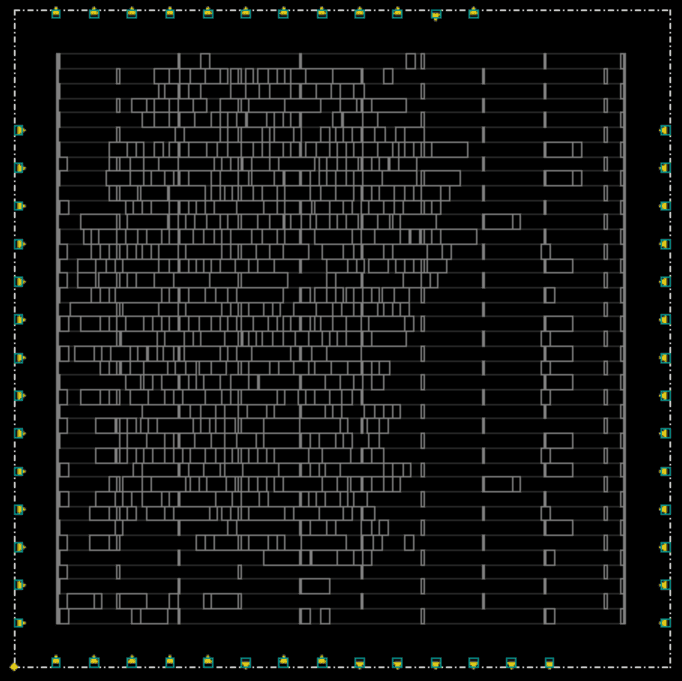
Initial floorplan

PDN
Netlist Optimization (Fix Fanout)
Execution Script <br>
./iEDA -script./script/iNO_script/run_iNO_fix_fanout.tcl
Parameter Configuration <br>
The path of the parameter configuration is in./iEDA_config/no_default_config_fixfanout.json, as follows
{
    "file_path": {
        "design_work_space": "./result/no",
        "sdc_file": "",
        "lib_files": "",
        "lef_files": "",
        "def_file": "",
        "output_def": "",
        "report_file": "./result/no/report.txt"
    },
    "insert_buffer": "sky130_fd_sc_hs__buf_8",
    "max_fanout": 30
}
The definitions of configurable Parameters are as follows
| Parameter Name | Default Value | Description |
|---|---|---|
| design_work_space | ./result/no | Set the working area path for the Fix Fanout running process |
| sdc_file | Invalid parameter, to be deleted later | |
| lib_files | Invalid parameter, to be deleted later | |
| lef_files | Invalid parameter, to be deleted later | |
| def_file | Invalid parameter, to be deleted later | |
| output_def | Invalid parameter, to be deleted later | |
| report_file | ./result/no/report.txt | The report generated during the Fix Fanout process |
| insert_buffer | sky130_fd_sc_hs__buf_8 | Set the name of the inserted buffer |
| max_fanout | 30 | The maximum Fanout count |
Input <br>
-./result/iFP_result.def
Output <br>
-./result/iTO_fix_fanout_result.def
-./result/iTO_fix_fanout_result.v
Evaluation and Report <br>
-./result/report/fixfanout_db.rpt
GUI <br>
step 1: Modify the input design def of the script./script/iGUI_script/run_iGUI.tcl to./result/iTO_fix_fanout_result.def
#===========================================================
##   read def
#===========================================================
def_init -path./result/iTO_fix_fanout_result.def
step 2: Execute the iEDA GUI script
./iEDA_gui -script./script/iGUI_script/run_iGUI.tcl
step 3: View the GUI
Placement
Execution Script <br>
./iEDA -script./script/iPL_script/run_iPL.tcl
Parameter Configuration <br>
Refer to iEDA_config/pl_default_config.json:
`./scripts/design/sky130_gcd/iEDA_config/pl_default_config.json`
| JSON Parameter | Function Description | Parameter Range | Default Value |
|---|---|---|---|
| is_max_length_opt | Whether to enable maximum wire length optimization | [0,1] | 0 |
| max_length_constraint | Specify the maximum wire length | [0-1000000] | 1000000 |
| is_timing_effort | Whether to enable timing optimization mode | [0,1] | 0 |
| is_congestion_effort | Whether to enable routability optimization mode | ||
| ignore_net_degree | Ignore nets with more than the specified number of pins | [10-10000] | 100 |
| num_threads | Specify the number of CPU threads | [1-64] | 8 |
| [GP-Wirelength] init_wirelength_coef | Set the initial wire length coefficient | [0.0-1.0] | 0.25 |
| [GP-Wirelength] reference_hpwl | Adjust the reference wire length for density penalty | [100-1000000] | 446000000 |
| [GP-Wirelength] min_wirelength_force_bar | Control the wire length boundary | [-1000-0] | -300 |
| [GP-Density] target_density | Specify the target density | [0.0-1.0] | 0.8 |
| [GP-Density] bin_cnt_x | Specify the number of Bins in the horizontal direction | [16,32,64,128,256,512,1024] | 512 |
| [GP-Density] bin_cnt_y | Specify the number of Bins in the vertical direction | [16,32,64,128,256,512,1024] | 512 |
| [GP-Nesterov] max_iter | Specify the maximum number of iterations | [50-2000] | 2000 |
| [GP-Nesterov] max_backtrack | Specify the maximum number of backtracks | [0-100] | 10 |
| [GP-Nesterov] init_density_penalty | Specify the density penalty in the initial state | [0.0-1.0] | 0.00008 |
| [GP-Nesterov] target_overflow | Specify the target overflow value | [0.0-1.0] | 0.1 |
| [GP-Nesterov] initial_prev_coordi_update_coef | The coefficient when perturbing the initial coordinates | [10-10000] | 100 |
| [GP-Nesterov] min_precondition | Set the minimum value of the precondition | [1-100] | 1 |
| [GP-Nesterov] min_phi_coef | Set the minimum phi parameter | [0.0-1.0] | 0.95 |
| [GP-Nesterov] max_phi_coef | Set the maximum phi parameter | [0.0-1.0] | 1.05 |
| [BUFFER] max_buffer_num | Specify the maximum number of buffers to be inserted | [0-1000000] | 35000 |
| [BUFFER] buffer_type | Specify the name of the buffer type that can be inserted | Process-related | List[...,...] |
| [LG] max_displacement | Specify the maximum displacement of cells | [10000-1000000] | 50000 |
| [LG] global_right_padding | Specify the spacing between cells (in units of Site) | [0,1,2,3,4...] | 1 |
| [DP] max_displacement | Specify the maximum displacement of cells | [10000-1000000] | 50000 |
| [DP] global_right_padding | Specify the spacing between cells (in units of Site) | [0,1,2,3,4...] | 1 |
| [Filler] first_iter | Specify the Filler used in the first iteration | Process-related | List[...,...] |
| [Filler] second_iter | Specify the Filler used in the second iteration | Process-related | List[...,...] |
| [Filler] min_filler_width | Specify the minimum width of the Filler (in units of Site) | Process-related | 1 |
| [MP] fixed_macro | Specify the fixed macro unit (string macro_name) | Design-related | List[...,...] |
| [MP] fixed_macro_coordinate | Specify the position coordinates of the fixed macro unit (int location_x, int location_y) | Design-related | List[...,...] |
| [MP] blockage | Specify the rectangular blocking area of the macro unit, and the macro unit should avoid being placed in this area (int left_bottom_x, int left_bottom_y, int right_top_x, int right_top_y) | Design-related | List[...,...] |
| [MP] guidance_macro | Specify the macro unit for guidance placement, and each macro unit can set the expected placement area (string macro_name) | Design-related | List[...,...] |
| [MP] guidance | Specify the guidance placement area corresponding to the macro unit (int left_bottom_x, int left_bottom_y, int right_top_x, int right_top_y) | Design-related | List[...,...] |
| [MP] solution_type | Specify the representation of the solution | ["BStarTree","SequencePair"] | "BStarTree" |
| [MP] perturb_per_step | Specify the number of perturbations per step in the simulated annealing | [10-1000] | 100 |
| [MP] cool_rate | Specify the cooling rate of the simulated annealing temperature | [0.0-1.0] | 0.92 |
| [MP] parts | Specify the number of partitions of standard cells (int) | [10-100] | 66 |
| [MP] ufactor | Specify the unbalance value of the standard cell partition (int) | [10-1000] | 100 |
| [MP] new_macro_density | Specify the density of the virtual macro unit | [0.0-1.0] | 0.6 |
| [MP] halo_x | Specify the halo in the horizontal direction of the macro unit | [0-1000000] | 0 |
| [MP] halo_y | Specify the halo in the vertical direction of the macro unit | [0-1000000] | 0 |
| [MP] output_path | Specify the output file path | "./result/pl" |
Input <br>
-./result/iTO_fix_fanout_result.def
Output <br>
-./result/iPL_result.def
-./result/iPL_result.v
Evaluation and Report <br>
-./result/report/pl_db.rpt
The intermediate reports of the iPL tool are stored in the directory by default:
./scripts/design/sky130_gcd/result/pl/
- report/violation_record.txt : Cells with layout violations
- report/wirelength_record.txt : Statistics of HPWL wire length, STWL wire length, and long wire length of the layout
- report/density_record.txt : Peak bin density of the layout
- report/timing_record.txt : Timing information of the layout (wns, tns), calling Flute for simple routing
GUI <br>
step 1: Modify the input design def of the script./script/iGUI_script/run_iGUI.tcl to./result/iPL_result.def
#===========================================================
##   read def
#===========================================================
def_init -path./result/iPL_result.def
step 2: Execute the iEDA GUI script
./iEDA_gui -script./script/iGUI_script/run_iGUI.tcl
step 3: View the GUI
Clock Tree Synthesis (CTS)
Execution Script <br>
./iEDA -script./script/iCTS_script/run_iCTS.tcl
Parameter Configuration <br>
| Parameter | Type | Description |
|---|---|---|
| skew_bound | Floating-point string | The maximum clock skew from the clock source to each register |
| max_buf_tran | Floating-point string | The maximum transition time constraint of the buffer |
| max_sink_tran | Floating-point string | The maximum transition time constraint of the register |
| max_cap | Floating-point string | The maximum load capacitance constraint |
| max_fanout | Integer string | The maximum fanout constraint |
| max_length | Integer string | The maximum wire length constraint |
| scale_size | Integer | The degree of division used to reduce the scale and accelerate the clock tree construction |
| buffer_type | String list | The list of buffer types available in the clock tree synthesis stage |
| routing_layer | Integer list | Specify the clock routing layers to obtain the unit capacitance and resistance information |
| use_netlist | String ("ON" or "OFF") | Whether to perform clock tree synthesis only on the nets in the "net_list". If this parameter is "OFF", clock tree synthesis is performed on all clock nets by default |
| net_list | String dictionary list | Specify the nets that need to undergo clock tree construction |
Input <br>
-./result/iPL_result.def
Output <br>
-./result/iCTS_result.def
-./result/iCTS_result.v
Evaluation and Report <br>
-./result/report/cts_db.rpt
GUI <br>
step 1: Modify the input design def of the script./script/iGUI_script/run_iGUI.tcl to./result/iCTS_result.def
#===========================================================
##   read def
#===========================================================
def_init -path./result/iCTS_result.def
step 2: Execute the iEDA GUI script
./iEDA_gui -script./script/iGUI_script/run_iGUI.tcl
step 3: View the GUI

Fix DRV Violation
Execution Script <br>
./iEDA -script./script/iTO_script/run_iTO_drv.tcl
Parameter Configuration <br>
Refer to "./scripts/design/sky130_gcd/iEDA_config/to_default_config_drv.json"
| Parameter Name | Default Value | Description |
|---|---|---|
| design_work_space | ./result/to | Set the working area path during the running process |
| sdc_file | Invalid parameter, to be deleted later | |
| lib_files | Invalid parameter, to be deleted later | |
| lef_files | Invalid parameter, to be deleted later | |
| def_file | Invalid parameter, to be deleted later | |
| output_def | Invalid parameter, to be deleted later | |
| report_file | ./result/to/report.txt | The report generated during the optimization process |
| gds_file | ./result/to/to.gds | The path of the generated GDS file. This file is not generated by default |
| setup_slack_margin | 0.0 | When the setup slack is less than this value, it is considered a violation and is also the target of slack optimization |
| hold_slack_margin | 0.0 | When the hold slack is less than this value, it is considered a violation and is also the target of slack optimization |
| max_buffer_percent | 0.2 | The maximum proportion of the area occupied by the inserted buffers in the chip area |
| max_utilization | 0.8 | The maximum proportion of the area occupied by the inserted buffers and other cells in the chip area |
| DRV_insert_buffers | sky130_fd_sc_hs__buf_8 | The buffers used for optimizing DRV. If not specified, they will be automatically selected from the buffer library |
| setup_insert_buffers | sky130_fd_sc_hs__buf_8 | The buffers used for optimizing setup. If not specified, they will be automatically selected from the buffer library |
| hold_insert_buffers | sky130_fd_sc_hs__buf_8 | The buffers used for optimizing hold. If not specified, they will be automatically selected from the buffer library |
| number_passes_allowed_decreasing_slack | 5 | The maximum consecutive iterations allowed for the WNS to deteriorate continuously during the iterative optimization of setup |
| rebuffer_max_fanout | 20 | For setup, when the fanout of a net exceeds this value, buffer insertion optimization will not be performed on it |
| split_load_min_fanout | 8 | For setup, when the fanout of a net is greater than this value, the fanout is reduced by inserting buffers |
Input <br>
-./result/iCTS_result.def
Output <br>
-./result/iTO_drv_result.def
-./result/iTO_drv_result.v
Evaluation and Report <br>
-./result/report/drv_db.rpt
Fix Hold Violation
Execution Script <br>
./iEDA -script./script/iTO_script/run_iTO_hold.tcl
Parameter Configuration <br>
Refer to "./scripts/design/sky130_gcd/iEDA_config/to_default_config_hold.json"
The detailed parameter information is the same as Fix DRV Violation
Input <br>
-./result/iTO_drv_result.def
Output <br>
-./result/iTO_hold_result.def
-./result/iTO_hold_result.v
Evaluation and Report <br>
-./result/report/hold_db.rpt
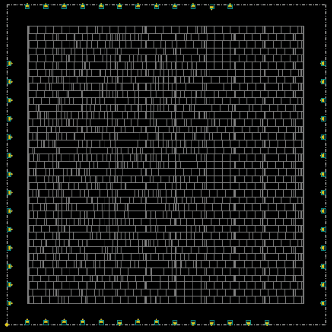
Cell Legalization
Execution Script <br>
./iEDA -script./script/iPL_script/run_iPL_legalization.tcl
Parameter Configuration <br>
Input <br>
-./result/iTO_hold_result.def
Output <br>
-./result/iPL_lg_result.def
-./result/iPL_lg_result.v
Evaluation and Report <br>
-./result/report/lg_db.rpt
GUI <br>
step 1: Modify the input design def of the script./script/iGUI_script/run_iGUI.tcl to./result/iPL_lg_result.def
#===========================================================
##   read def
#===========================================================
def_init -path./result/iPL_lg_result.def
step 2: Execute the iEDA GUI script
./iEDA_gui -script./script/iGUI_script/run_iGUI.tcl
step 3: View the GUI
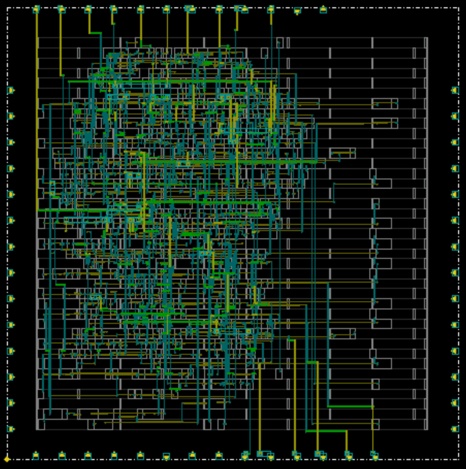
Routing
Execution Script <br>
./iEDA -script./script/iRT_script/run_iRT.tcl
Parameter Configuration <br>
Input <br>
-./result/iPL_lg_result.def
Output <br>
-./result/iRT_result.def
-./result/iRT_result.v
Evaluation and Report <br>
-./result/report/rt_db.rpt
GUI <br>
step 1: Modify the input design def of the script./script/iGUI_script/run_iGUI.tcl to./result/iRT_result.def
#===========================================================
##   read def
#===========================================================
def_init -path./result/iRT_result.def
step 2: Execute the iEDA GUI script
./iEDA_gui -script./script/iGUI_script/run_iGUI.tcl
step 3: View the GUI
Cell Filler
Execution Script <br>
./iEDA -script./script/iPL_script/run_iPL_filler.tcl
Parameter Configuration <br>
Input <br>
-./result/iRT_result.def
Output <br>
-./result/iPL_filler_result.def
-./result/iPL_filler_result.v
Evaluation and Report <br>
-./result/report/filler_db.rpt
GUI <br>
step 1: Modify the input design def of the script./script/iGUI_script/run_iGUI.tcl to./result/iPL_filler_result.def
#===========================================================
##   read def
#===========================================================
def_init -path./result/iPL_filler_result.def
step 2: Execute the iEDA GUI script
./iEDA_gui -script./script/iGUI_script/run_iGUI.tcl
step 3: View the GUI
DEF to GDSII
Execution Script <br>
./iEDA -script./script/DB_script/run_def_to_gds_text.tcl
Parameter Configuration <br>
Input <br>
-./result/iPL_filler_result.def
Output <br>
-./result/final_design.gds2
GUI Operation Manual
Running the GUI
Compilation and Construction
step 1: Modify the compilable options
Switch to the iEDA project directory
# Switch to the iEDA project directory
cd iEDA
Set BUILD_GUI in the top-level CMakelist.txt to ON
# Set BUILD_GUI in the top-level CMakelist.txt to ON
option(BUILD_GUI "If ON, build GUI." ON)
step 2: Compile and build
# Install compilation dependencies via apt, requires root privileges
sudo bash build.sh -i apt
# Compile iEDA
bash build.sh -j 16
step 3: Copy the copy as iEDA_gui
# Copy iEDA to the sky130 directory
cp./bin/iEDA scripts/design/sky130_gcd/iEDA_gui
Configure the Design File
Modify the input design def of the script./script/iGUI_script/run_iGUI.tcl to the design file to be viewed, such as modifying it to./result/iFP_result.def
#===========================================================
##   read def
#===========================================================
def_init -path./result/iFP_result.def
Run the GUI
Execute the iEDA GUI script
./iEDA_gui -script./script/iGUI_script/run_iGUI.tcl
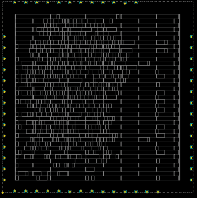
Visualization
The following figure shows the visualization result of reading the./result/iFP_result.def design file